From 2D to 3D: Using Reconstructed Geometry for Manufacturing Analysis
August 24, 2026
A 2D-to-3D conversion is useful only if the resulting geometry can support the next engineering task. For legacy parts, spare parts and components with missing CAD, the usual problem is not simply the absence of a 3D file. Without usable geometry, it is difficult to run automated manufacturability checks, compare production processes, estimate should-cost, or evaluate lead time. 3D Spark uses 2D-to-3D reconstruction as the entry point into this wider analysis workflow.
The technical sequence is:
2D drawing or image → reconstructed 3D geometry → process feasibility → should-cost → technology comparison → lead time and CO₂ → make-or-buy
The 3D model is therefore not the end result. It is the geometry required for the downstream engineering calculations.
Recovering usable geometry when CAD is missing
When a valid 3D CAD model already exists, it can be used directly. When it does not, the available input may be:
A technical drawing
PDF
Scanned drawing
JPG or PNG image
Photograph of the physical component
DXF or DWG
Multiple sources describing the same part
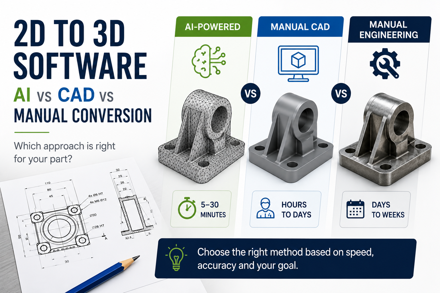
3D Spark's Voluminate product can reconstruct an NNS Model (Near-Net-Shape Model), from this source data. The NNS Model is delivered as STL geometry and is typically generated within 5 to 30 minutes. It is important to understand what this geometry represents.
The NNS model is:
AI-generated
Not dimensionally verified
Not reviewed by a design engineer
Intended for analysis and screening
Potentially incomplete if the source data is incomplete
If a production ready model is required then Voluminate can also continue by providing a Hi-Fi CAD model, where an expert design engineer also refines and dimensionally verifies the reconstruction after the AI model is generated. For the analysis stage, however, the main requirement is often different: the geometry needs to represent the part sufficiently well for process evaluation.
Why 3D geometry matters for manufacturability analysis
A manufacturing process cannot be selected reliably from a part number, description or bounding box alone. The geometry itself affects whether a process is technically suitable. Depending on the process, relevant characteristics can include:
Overall part dimensions
Part volume
Surface area
Wall thickness
Holes and pockets
Aspect ratios
Undercuts
Overhangs
Geometric accessibility
Material removal volume
Build orientation
Process-specific dimensional limits
Once usable 3D geometry exists, 3D Spark can evaluate the component against process-specific manufacturing constraints. The question changes from:
Can we reconstruct the part?
to:
Which processes can manufacture this geometry?
This is the first point where 2D-to-3D becomes technically useful beyond visualization.
Process feasibility before process selection
A manufacturing technology should not be compared economically until it is technically feasible.
For example, a process may be excluded because:
The part exceeds the available machine envelope
A feature cannot be accessed by the tool
A wall is below the practical process limit
An undercut requires additional operations
The geometry creates an unsuitable build orientation
Post-processing requirements make the route impractical
3D Spark evaluates manufacturing technologies using process-specific constraints so that unsuitable routes can be filtered before cost comparison. This is especially relevant for legacy parts because the original manufacturing route may no longer be the best one. The fact that a part was originally cast or machined does not mean that the same process remains technically or economically optimal today.
From feasible process to should-cost
Once a process is technically feasible, the next question is cost. 3D Spark uses process-based costing rather than relying only on historical purchase prices. Depending on the technology, a should-cost model can include components such as:
Material cost
Setup time
Machine time
Labour
Tooling or process preparation
Post-processing
Process overhead
The geometry influences several of these inputs. For machining, for example, part size, stock volume, material removal and accessibility can affect process time and cost. For additive manufacturing, build volume, orientation, support requirements and build time can influence the calculation. This is why reconstructing the geometry matters. The 3D model provides the technical basis for a process-level estimate rather than a rough price extrapolated from dimensions alone.
Comparing manufacturing technologies on the same geometry
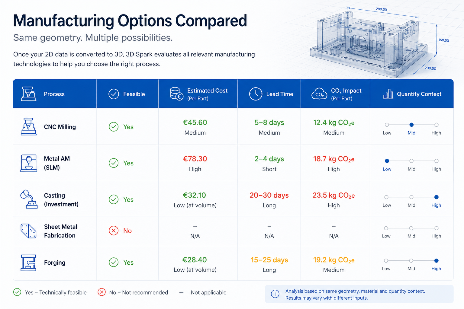
Once the component has been reconstructed, the same geometry can be evaluated across multiple manufacturing technologies. This allows an engineer to compare alternatives using a consistent part definition. A simplified comparison might look like:
The useful output is not simply a list of possible processes. It is a technically filtered comparison of:
Feasibility + cost + lead time + CO₂
This allows the manufacturing route to be selected based on the actual geometry and production requirement.
Quantity changes the result
Manufacturing decisions are rarely independent of quantity.
A process that is economical for one or ten parts may not be competitive at 500 parts.
The analysis therefore needs to account for factors such as:
Setup cost
Tooling cost
Machine utilization
Cycle time
Batch size
Material usage
Post-processing
Quantity-dependent cost distribution
This is particularly relevant for spare parts. Low-volume demand can make processes with high tooling investment unattractive, even if those processes were originally used for series production.
Reconstructing the part and comparing current production routes can reveal a different optimum for today's quantity.
Lead time as an engineering constraint
Cost is not always the dominant criterion. For a maintenance component, a long lead time can create more operational risk than a higher unit price. Once the part is geometrically defined and feasible manufacturing routes have been identified, lead time can be evaluated alongside cost. An engineer or sourcing team can then compare, for example:
Route A: lower part cost, long tooling and production lead time
Route B: higher unit cost, no tooling, significantly shorter lead time
For critical spare parts, this trade-off can be more relevant than unit price alone.
CO₂ as another process output
3D Spark can also evaluate CO₂ impact for manufacturing alternatives. The same part geometry can therefore be compared across:
Technical feasibility
Manufacturing cost
Lead time
CO₂
This is useful because process selection often involves trade-offs rather than one universally best solution. A manufacturing route may be cheaper but slower. Another may have a shorter lead time but higher energy demand. The geometry provides the common technical basis for comparing those options.
From technical analysis to make-or-buy
Once a feasible manufacturing route and should-cost are available, the analysis can support a make-or-buy decision. For internal production, the question is:
Can our equipment manufacture the part, and at what cost?
For external sourcing:
What should a supplier reasonably charge for this geometry, material, process and quantity?
The result gives engineering and procurement a common technical reference.
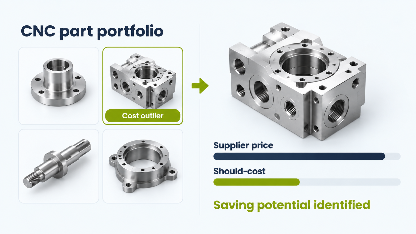
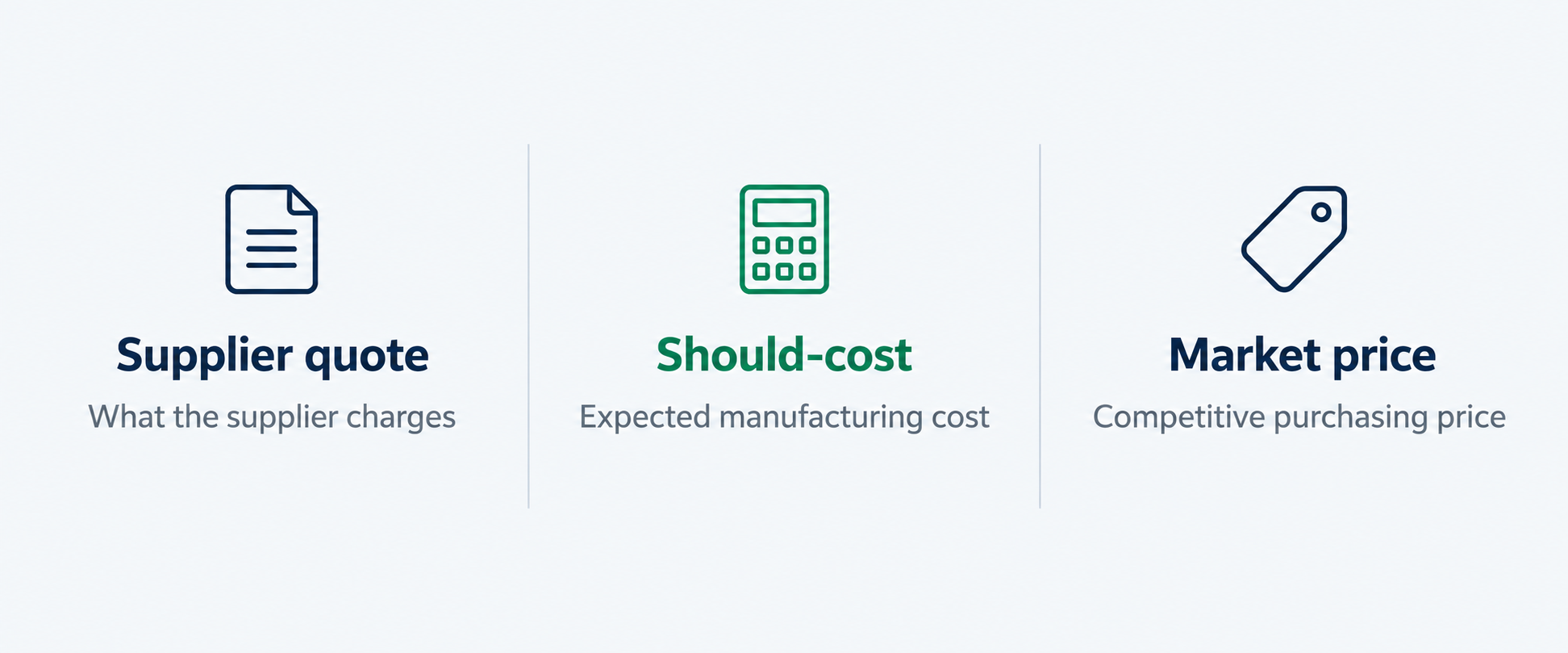
Instead of comparing supplier quotations without an independent baseline, the team can compare the quoted price against a process-based should-cost.
Where Hi-Fi CAD becomes necessary
The NNS Model is suitable when the purpose is analysis. The requirements change when the part moves toward final engineering or production. At that stage, the model may need:
Dimensional verification
Correction of uncertain features
Exact interfaces
Tolerance definition
Design modification
Controlled engineering release
For these cases, 3D Spark provides Hi-Fi CAD. Hi-Fi CAD uses the AI-generated reconstruction as a starting point and adds expert engineering refinement and verification. The result is an editable STEP model intended for production use.
This creates two clearly different levels of geometry:
NNS Model → analysis geometry
Hi-Fi CAD → verified engineering geometry
The correct choice depends on the downstream task.
2D-to-3D as an input layer for manufacturing intelligence
The main technical value of 2D-to-3D inside 3D Spark is therefore straightforward. It converts legacy information into geometry that the manufacturing analysis engine can use.
Without CAD:
Drawing or image → limited automated analysis
With reconstructed geometry:
3D model → feasibility → should-cost → process comparison → lead time → CO₂ → make-or-buy
That is the role of the 2D-to-3D feature. It does not replace manufacturing engineering. It removes the missing-CAD barrier so that engineering analysis can begin earlier.
Start with the geometry you have
If the original CAD model is missing, start with the available technical drawing, scan or part image.
Try 2D-to-3D with 3D Spark and use the reconstructed geometry as the input for further manufacturing analysis.
Convert your file for free or Book a demo!
Upload your part and get started for free
Try our platform for free by uploading your 2D and receive it's 3D version!
With features to make every step of your manufacturing business more efficient and scalable, coupled with a support team excited to help you, getting started with 3D Spark has never been easier.


)%20(1).avif)